Electrical Resistivity Method
Het doel van de elektrische weerstands methode is om de elektrische waardes van de ondergrond te meten, De elektrische weerstand is een functie van een groot aantal eigenschappen van de ondergrond (zoals water hoeveelheid, lithologie, biogeochemische processen, temperatuur) en de distributie van elektrische waardes in de ondergrond kan worden geinterpreteerd in de context van deze eigenschappen.
De standaard methode om de elektrische weerstand te meten is door een vier elektrode meting. In de sectie hieronder is wat meer detail te vinden over deze methode en de metingen. Deze pagina van Subsurface Insights en links hier hebben meer details over de elektrische weerstandsmethode (electrical resistivity in het engels).
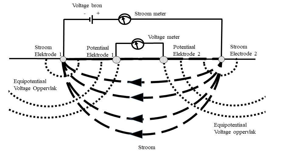
In a four electrode measurement we apply a direct current voltage across two electrodes (these are the current electrodes). This creates a current and potential field in the substrate and we can measure both the current and the electrical potential across two other electrodes (the potential electrodes). From the current (in Amperes) and potential (in Volts) we can now calculate a transfer resistance with Ohm's law (R=V/I). This resistance is a function of the electrical resistance of the matrix and the liquid. In the case where we have a matrix of sand (where sand effectively has a high resistivity) and where we have as liquid water with a large amount of ions (eg salt water, or even in many cases just groundwater) the influence of the water dominates and we can do a measurement that (under certain conditions and assumptions) gives us direct information about the electrical conductivity of the water in a certain area in the subsurface – something that can be translated into the presence of fresh, brackish or salt water.
Resistivity measurements on a multi-electrode cable
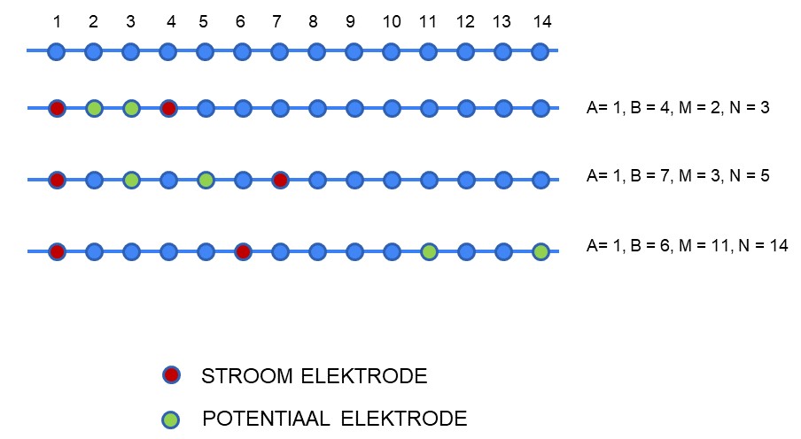
In a standard measurement we use a set of four electrodes. In order to obtain information about the substrate, we have to make many measurements with electrodes in different positions. This can be done either by moving the electrodes or by using cables with multiple (typically 12-30) conductors inside that are all attached to a different electrode along the cable. At the end of this cable is a connection with metal pins (where each pin is connected to a conductor in the cable, and from there to an electrode), and we can then - by attaching our instrument to four of these pins - make a measurement with different electrodes. In this measurement we use both a simple numbering of the electrodes (often 1, 2,3..) and the ABMN convention, in which A and B indicate which electrodes are the current electrodes, and which electrodes are the potential electrodes.
The figure below shows an example of a simple cable with fourteen electrodes, and three measurements. In this figure, the red electrodes are the current electrodes and the green electrodes are the potential electrodes.