Standaard zoutwachter metingen
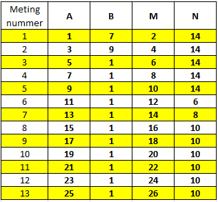
A standard salt guardian cable has twenty-six electrodes. As is shown here, is kunnen we metingen doen met verschillende combinaties van vier elektrodes aan dezekabel. Historisch worden er dertien metingen gemaakt aan een zoutwachter kabel. Het doel van deze metingen is om een beeld te geven van de zoutwater dynamiek.
Why do we do collect these specific measurements?
One question which is of interest is why these specific thirteen measurements are being collected. This measurement protocol was established in the 1970s and is described on page 16 in the report Fysisch boorgatonderzoek: metingen door middel van diverse meetsystemen, waaronder “Zoutwachters“, F. Walter, 1970, PN-70-003. Dit rapport verwijst naar de originele analoge meetapparatuur voor zoutwachters. Deze bestond uit een instrument met een keuzeschakelaar met met dertien verschillende standen die aan een zoutwachter kabel gekoppeld werd.
Uit dit rapport schijnt dat er ook kabels waren met 14 elektrodes en zeven meetpunten, maar in de praktijk schijnt dat voornamelijk de kabel met 26 elektrodes gebruikt is.
In elke stand was het meet instrument met vier verschillende elektrodes verbonden. Dat laat nog steeds de vraag – waarom specifiek deze dertien metingen? Dit kan ten dele verklaard worden door te kijken naar de geometrische faktor.
Geometric Factor
It is clear that if we place the potential electrodes closer together we will generally measure a smaller potential difference. What this means is that the transfer resistance depends on the geometry of the measurement. To remove this dependence we can correct the measurements with a geometric factor (Kg). This is defined as
Kg = 4π((1/C1P1) − (1/C1P2) − (1/C2P1) + (1/C2P2))-1
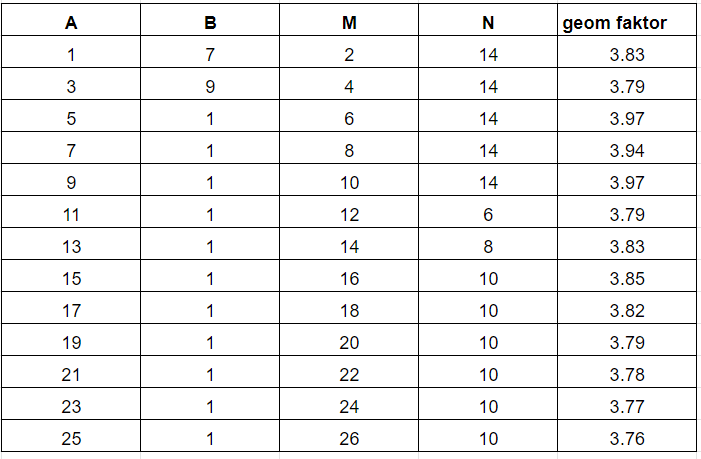
In this formula C1 and C2, and P1 and P2 are the positions of the current and potential electrodes and C1P1 is the distance between C1 and P1, C1P2 is the distance between C1 and P2 and so forth. The values of the geometric factor for a distance of 30 cm between the electrodes in a pair and a distance of 3 meters between pairs can be seen in the table on the right. We can then calculate the apparent resistivity from the transfer resistance multiplied by the geometric factor.
The conclusion is that for all the standard salt keeper measurements the geometric factor is about the same.
This conclusion is the same for other distance combinations (eg 15 cm between electrodes in a pair and 5 meters between pairs).
The advantage of the geometric factor being the same is that we can directly compare the measurements, and so these measurements can be used directly to give a relative picture of the change in electrical resistance with depth (and also used can be used to estimate eg the chloride concentration).
This explains the reason for these specific thirteen measurements. More detail on the interpretation of the Salt Guardian data can be found in the next section.
A detail is that the formula gives the geometric factor for borehole electrodes. Such as is described in this article the geometric factor for borehole electrodes is twice that of surface electrodes.